

 中文简体
中文简体 русский
Single and Double Head Chamfering Machine Explained: How to Choose, Set Up, and Get the Most Out of Either One
 2026.05.26
 Industry News
Content
- 1 What a Chamfering Machine Actually Does and Why It Matters in Production
- 2 Single Head Chamfering Machine: How It Works and When to Use It
- 3 Double Head Chamfering Machine: Simultaneous Processing for High-Volume Lines
- 4 Single Head vs. Double Head: Choosing the Right Configuration
- 5 Chamfer Angle and Depth: Getting the Specifications Right
- 6 Automation and Integration in Modern Chamfering Machines
- 7 Key Specifications to Evaluate When Selecting a Chamfering Machine
- 8 Maintenance Practices That Protect Machine Accuracy and Tool Life
What a Chamfering Machine Actually Does and Why It Matters in Production
A chamfering machine is a dedicated piece of metalworking equipment designed to cut a precise beveled edge — called a chamfer — along the end or perimeter of a workpiece. That beveled edge is not decorative. It removes the sharp burr or corner left after cutting, sawing, or turning, and prepares the workpiece for the next process: welding, threading, pressing into an assembly, or final inspection. A chamfered edge reduces stress concentration at part edges, prevents seal damage during assembly, and ensures components fit together accurately in tight-tolerance applications.
While chamfering can be done manually with a file or on a CNC machining center, a dedicated chamfering machine — whether a single head or double head model — delivers consistent angle, depth, and surface quality across high production volumes at a fraction of the cycle time. The difference between single and double head configurations determines how many ends of a workpiece can be processed per cycle, which has a direct impact on throughput, labor requirements, and cost per part.
Single Head Chamfering Machine: How It Works and When to Use It
A single head chamfering machine processes one end of a workpiece per cycle. The workpiece — typically a metal bar, pipe, shaft, or tube — is clamped or fed into position, and a single rotating cutting head applies the chamfer at the specified angle and depth. After the cut, the part is either manually repositioned or advanced by an automated feeding system before the next cycle begins.
The single head chamfering machine is the standard choice for operations where one-end processing is sufficient — for example, pipes that are threaded on one end only, fasteners that require a lead-in chamfer on the tip, or components where only the feed end requires edge preparation before welding. It is also the practical choice for shops running lower volumes, mixed part families, or prototype batches, where the lower capital cost and simpler setup of a single head unit are more important than maximum throughput.
Key Advantages of Single Head Configuration
Single head chamfering machines are compact, straightforward to operate, and significantly less expensive than double head equivalents. Setup involves mounting the appropriate chamfering tool, setting the angle (most commonly 30°, 45°, or 60°) via a graduated adjustment mechanism, and setting the depth stop. For shops processing a wide variety of part sizes and geometries, the single head machine's simpler changeover makes it faster to adapt between jobs. Pneumatic single head models are particularly valued for their precise air pressure control, which allows operators to adjust the feed force and achieve consistent chamfer dimensions on every part without manual variation.
Typical Applications
Single head chamfering machines are commonly used in pipe fabrication, fastener manufacturing, hydraulic component production, and general job shop metalworking. They handle solid bars, hollow tubes, and special-profile extrusions, with cutting diameter ranges typically from 3 mm to 150 mm depending on the machine model and tooling configuration.
Double Head Chamfering Machine: Simultaneous Processing for High-Volume Lines
A double head chamfering machine mounts two cutting heads — one at each end of the workpiece travel path — so that both ends of the part are chamfered in a single clamping and feed cycle. The workpiece enters the machine, is gripped by the clamping system, advances through the cutting zone, and exits fully chamfered on both ends without any manual repositioning. This is the core operational advantage: a single positioning completes the full end-processing requirement, eliminating the second setup, second clamping, and secondary calibration that a single head machine requires for the same result.
For production lines processing high volumes of cut-to-length bars, pipes, or shafts — where both ends consistently require chamfering — the double head chamfering machine effectively halves the processing cycle compared to running two passes through a single head machine. In a production environment generating thousands of parts per shift, this cycle time reduction translates directly into lower labor costs, higher machine utilization, and reduced work-in-process inventory between operations.
Clamping, Feeding, and Dimensional Control
The clamping system on a double head chamfering machine must hold the workpiece rigidly against the cutting forces from two simultaneous cutting heads operating at opposite ends. This requires a more robust clamping design than a single head unit — typically hydraulic or pneumatic vise-type clamps with V-block or roller-type work supports that self-center the part regardless of diameter variation within the machine's capacity range. The distance between the two cutting heads is adjustable to accommodate different workpiece lengths, and high-end models allow this head-spacing adjustment via servo-driven positioning with digital readout, enabling fast changeover between part lengths without manual measurement.
Industries and Applications
Double head chamfering machines are standard equipment in automotive parts manufacturing, construction hardware production, hydraulic cylinder component lines, and any facility processing cut-to-length pipe or bar stock at volume. They are particularly prevalent in tube and pipe processing — where finished-length tubes are cut from coil or bar stock and both ends require chamfering for threading, swaging, or fitting assembly — and in the production of threaded fasteners, connecting rods, and suspension components where both end faces require precise edge preparation before downstream processing.
Single Head vs. Double Head: Choosing the Right Configuration
The decision between a single head and double head chamfering machine comes down to production volume, part geometry, and the end-processing requirements of the specific workpiece. Neither configuration is universally superior — the right choice depends on the specifics of the application.
| Factor | Single Head Chamfering Machine | Double Head Chamfering Machine |
|---|---|---|
| Ends processed per cycle | One | Two (simultaneous) |
| Cycle time for both ends | Two setups or passes required | Single pass — both ends done |
| Best production volume | Low to medium | Medium to high |
| Footprint | Compact | Larger (dual-head frame) |
| Setup complexity | Simple, fast changeover | More parameters; head spacing, dual tool setup |
| Capital cost | Lower | Higher |
| Labor per part | Higher (repositioning required) | Lower (single load/unload per part) |
| Ideal for | Job shops, mixed part families, one-end chamfering | Dedicated production lines, cut-to-length stock, both-end processing |
A useful decision rule: if more than 60–70% of your chamfering work requires processing both ends of the workpiece, and volumes are sufficient to justify the capital investment, a double head chamfering machine will reduce per-part cost. If your volume is lower, your part mix is diverse, or only one end of most workpieces requires chamfering, a single head machine — possibly supplemented by a second unit for specific jobs — is typically the better economic choice.
Chamfer Angle and Depth: Getting the Specifications Right
The most common chamfer angle across industrial metalworking is 45°, which provides a balanced bevel that works well for threading preparation, weld joint access, and general assembly lead-in. However, 30° and 60° chamfers are also frequently required — 30° is used for weld prep on thicker-walled pipe where a shallower angle creates a wider joint root, and 60° is common in hydraulic and pneumatic fitting interfaces where a narrow, deep bevel provides a sealing geometry. Most chamfering machines — both single and double head models — accommodate angle adjustments through a graduated tilting spindle head or swappable tooling inserts that preset the cutting geometry.
Chamfer depth is equally critical and must be controlled to tight tolerances on parts that feed into automated assembly. A chamfer that is too shallow provides insufficient lead-in for press fitting or threading; a chamfer that is too deep removes material from the functional end-face and can affect the part's overall length tolerance. Depth control on modern chamfering machines is handled by a mechanical depth stop, servo-controlled feed axis, or hydraulic feed with a preset pressure cutoff — the appropriate mechanism depends on the required tolerance band and production rate.
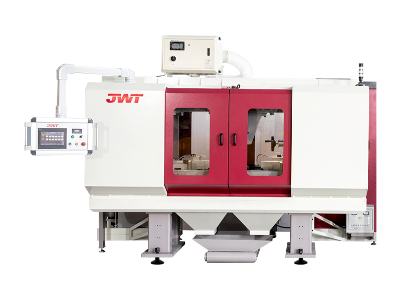
Material-Specific Considerations
Material hardness, ductility, and chip behavior all affect chamfering performance. Mild steel and aluminum produce short, controllable chips and are straightforward to chamfer at standard cutting speeds. Stainless steel is more work-hardening than mild steel and requires sharper tooling, slower feed rates, and adequate coolant to prevent built-up edge on the cutting tool. Hardened steel components may require carbide-tipped or coated inserts rather than standard HSS tooling. Thin-walled tubes present a different problem — the workpiece can deflect or collapse under excessive clamping or cutting force, requiring lighter feed pressure and broader clamping support to maintain dimensional control.
Automation and Integration in Modern Chamfering Machines
Both single head and double head chamfering machines are available in manual, semi-automatic, and fully automatic configurations. The appropriate level of automation depends on production volume, consistency requirements, and available labor. Understanding what each level actually provides helps avoid both over-specifying (paying for automation features that the production volume doesn't justify) and under-specifying (creating a bottleneck in an otherwise automated line).
Manual and Semi-Automatic Models
Manual chamfering machines require the operator to load, position, clamp, advance the cutting head, and unload the workpiece for every cycle. They offer maximum flexibility and the lowest cost, but output is directly limited by operator speed and fatigue. Semi-automatic models automate the cutting cycle — the operator loads and positions the part, then the machine executes the feed, cut, and retract automatically before releasing the part. This eliminates variability in the cutting portion of the cycle while keeping the loading step manual, which is appropriate for medium-volume applications or parts that are difficult to automate for loading.
Fully Automatic and CNC-Controlled Chamfering Machines
Fully automatic chamfering machines integrate a magazine or conveyor feed system that loads parts without operator intervention, processes them through the chamfering cycle, and deposits finished parts in an output bin or directly onto the next conveyor. CNC-controlled models add the ability to store multiple job programs — each with its own angle, depth, feed rate, and spindle speed settings — that can be recalled instantly when switching between part numbers. This programmability eliminates manual angle and depth readjustment during changeover, which is particularly valuable on double head chamfering machines where two cutting heads must both be reconfigured simultaneously. Advanced models include automatic tool wear compensation, which adjusts feed depth incrementally as the cutting tool wears to maintain consistent chamfer dimensions without manual intervention.
Integration with Cutting Lines
In high-volume bar and pipe processing, chamfering machines are frequently integrated directly downstream of cut-off saws or cold shears. Parts exit the cutting machine, pass through a transfer conveyor or vibratory feeder, enter the chamfering machine for end processing, and continue to the next station — threading, inspection, or packaging — without any manual handling. Double head chamfering machines are particularly suited to this inline configuration because the single-pass, both-ends processing matches the continuous flow of a production line. Single head machines in inline configurations require either a part flip station between two machines or a rotary indexing fixture to present the second end to the cutting head.
Key Specifications to Evaluate When Selecting a Chamfering Machine
When sourcing a single head or double head chamfering machine — whether for a new production line or as a replacement for an existing unit — the following specifications should be evaluated against your actual workpiece range and production requirements before comparing prices or brands.
- Workpiece diameter range: Confirm that both the minimum and maximum diameters of your parts fall comfortably within the machine's rated capacity, with room for future product changes. Most machines list both the mechanical range and the tooling range separately.
- Workpiece length range (double head): The minimum and maximum distance between the two cutting heads must span the full length range of your cut parts. Verify whether head spacing adjustment is manual or servo-driven, and how long changeover takes.
- Chamfer angle adjustment range: Confirm the machine supports all angles your parts require — typically 15° to 60° — and check whether angle changes require tool swap or are accomplished by adjusting the head angle directly.
- Spindle speed and feed control: Variable spindle speed allows the machine to be optimized for different materials. Controlled feed rate — rather than fixed manual advance — improves surface finish and extends tool life, particularly on stainless steel and harder alloys.
- Clamping system type: Hydraulic clamping provides consistent grip force regardless of operator variation; pneumatic is faster for lighter workpieces. Evaluate whether the clamping system accommodates your part geometry — round bars, square profiles, and thin-wall tubes each have different clamping requirements.
- Coolant system: For steel and stainless steel, flood coolant or minimum quantity lubrication (MQL) significantly extends insert life and improves surface finish. Verify whether the machine includes an integrated coolant system or requires external provision.
- Tooling compatibility: Confirm the machine accepts standard indexable insert tooling from multiple suppliers, not only proprietary tooling from the machine manufacturer. Proprietary tooling creates long-term cost and supply chain dependency.
Maintenance Practices That Protect Machine Accuracy and Tool Life
Chamfering machine accuracy depends on the condition of the spindle bearings, the rigidity of the clamping system, and the sharpness of the cutting tooling. Neglecting any of these three areas degrades chamfer quality in ways that may not be immediately visible but show up as dimensional rejects during downstream inspection or assembly problems in the field.
Spindle bearings should be checked for play and noise at scheduled intervals — typically every 500 to 1,000 operating hours depending on the machine's duty cycle and the materials being cut. Any radial or axial play in the spindle translates directly into runout at the cutting edge, producing inconsistent chamfer depth and rougher surface finish. Clamping components — jaws, V-blocks, and locating surfaces — should be inspected for wear and chip buildup after every shift. Chips embedded in the clamping surfaces cause workpiece misalignment that produces angular errors in the chamfer even when the cutting head is correctly set.
Cutting inserts should be indexed or replaced before they reach the end of their cutting life, not after. Dull tooling increases cutting force, causes workpiece deflection in thin-wall applications, and produces a poor surface finish that may require additional deburring. Maintaining a consistent insert replacement schedule — tracked by number of parts cut rather than time — is the most reliable way to keep chamfer quality consistent across shifts and operators on both single and double head chamfering machines.
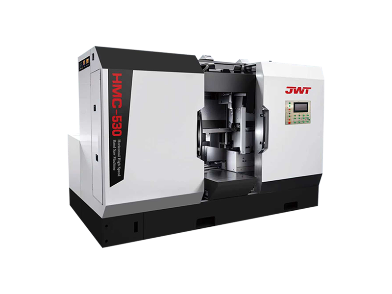
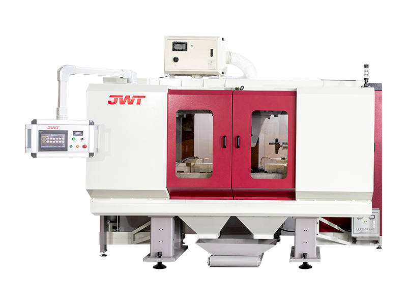
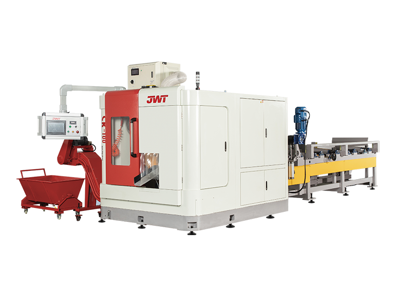
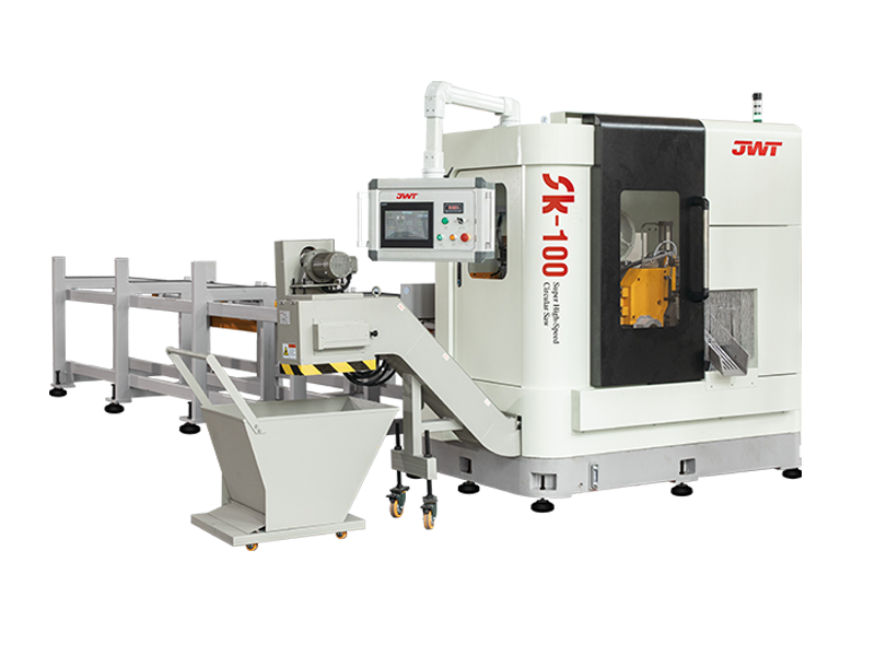

If you are interested in our Circular Saw Machine or production line, please consult us
CONTACT DETAILS
Zhejiang Jingweite Machine Tool Co.,Ltd.
- No.661 Jiyi Road, Wanghai Hi-tech Industrial Park, Haiyan, Jiaxing City, Zhejiang Province
- TEL:+86-0573-86035661
- E-Mail: [email protected]
Products
Quick link
Mobile terminal
